
Learning how to measure ute tray fitment correctly is the single most critical preliminary step when building or installing a custom flat tray on a four-wheel drive utility vehicle. Whether you are replacing a factory sheet metal tub or fitting a precision CNC laser-cut tray kit, getting every chassis measurement right ensures your subframe aligns perfectly with factory mounting points. Incorrect measurements can lead to chassis bracket misalignment, tire scrubbing against mudguards, legal overhang violations, and compromised vehicle handling caused by improper weight distribution over the rear axle.
For dual cab, extra cab, and single cab 4WD owners, mastering how to measure ute tray fitment prevents costly fabrication mistakes during workshop assembly. Chassis mounting dimensions, crossmember spacing, fuel filler neck clearances, and cab-to-tray gap tolerances vary significantly between vehicle models such as the Toyota HiLux, Ford Ranger, Isuzu D-Max, and Mitsubishi Triton. Understanding how to measure ute tray fitment allows you to design longitudinal main runners that sit securely on factory chassis isolation pads without interfering with shock absorber towers or brake line brackets.
In this technical measuring guide, we detail every step required to assess your vehicle chassis frame. From mapping mounting bracket hole centers and checking chassis squareness to calculating legal rear overhang limits, clearance zones, and electrical loom pathways, this guide provides the exact process for how to measure ute tray fitment.
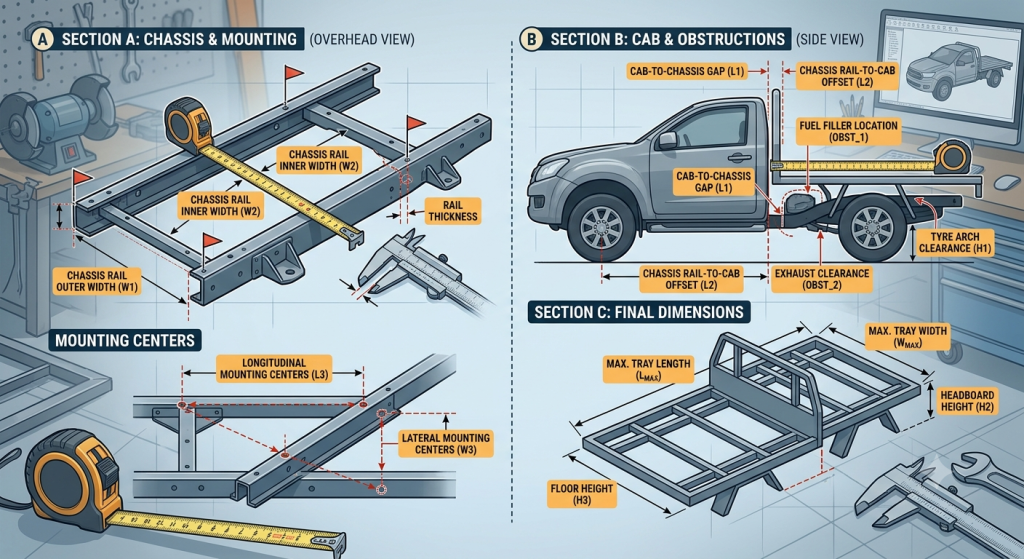
Before picking up a tape measure, understanding the reference geometry is essential when learning how to measure ute tray fitment.
                [ Technical Chassis Geometry & Measurement Reference ]
                                           │
  ┌────────────────────────────────────────┴────────────────────────────────────────┐
  ▼                                                                                 ▼
[ Longitudinal Alignment Axis ]                                   [ Transverse Clearance & Center Axis ]
• Rear Cab Clearance Gap (30mm – 50mm flex buffer)                • Chassis Outer Rail Width (Outer-to-Outer)
• Axle Centerline to Rearmost Chassis Point                       • Mounting Bracket Hole Pitch & Height Relative to Cab
• Overall Tray Length (1,500mm Dual Cab / 2,400mm Single Cab)     • Wheel Track Center & Arch Clearance Arc Radius
• Maximum Permissible Rear Overhang (60% Wheelbase Limit)         • Fuel Filler Neck Projection Angle & Breathing Tube Routing
When studying how to measure ute tray fitment, establish a fixed reference line—known as a datum point—on your vehicle frame. The rear cab wall serves as the primary longitudinal reference line, while the rear axle centerline acts as the primary balance datum. Measuring all lengths from these consistent reference points prevents cumulative measurement errors when fabricating your tray runners and crossmembers.
In addition, understanding how to measure ute tray fitment involves accounting for chassis flex. Utility vehicle frames are engineered to twist and flex during offroad cross-axle articulation. Maintaining a minimum clearance gap of 30mm to 50mm between the back of the cabin wall and the front headboard frame of your tray prevents panel damage when driving across uneven terrain.
Accurately mapping your vehicle’s rear frame requires a structured measuring process. Here are the seven essential steps when learning how to measure ute tray fitment:
The first step in how to measure ute tray fitment is measuring from the rearmost point of the cabin wall to the front face of your proposed tray headboard, ensuring a 30mm to 50mm dynamic flex buffer.
Determining runner spacing requires measuring the outer-edge-to-outer-edge width across your vehicle’s main frame rails. This measurement forms a core part of how to measure ute tray fitment.
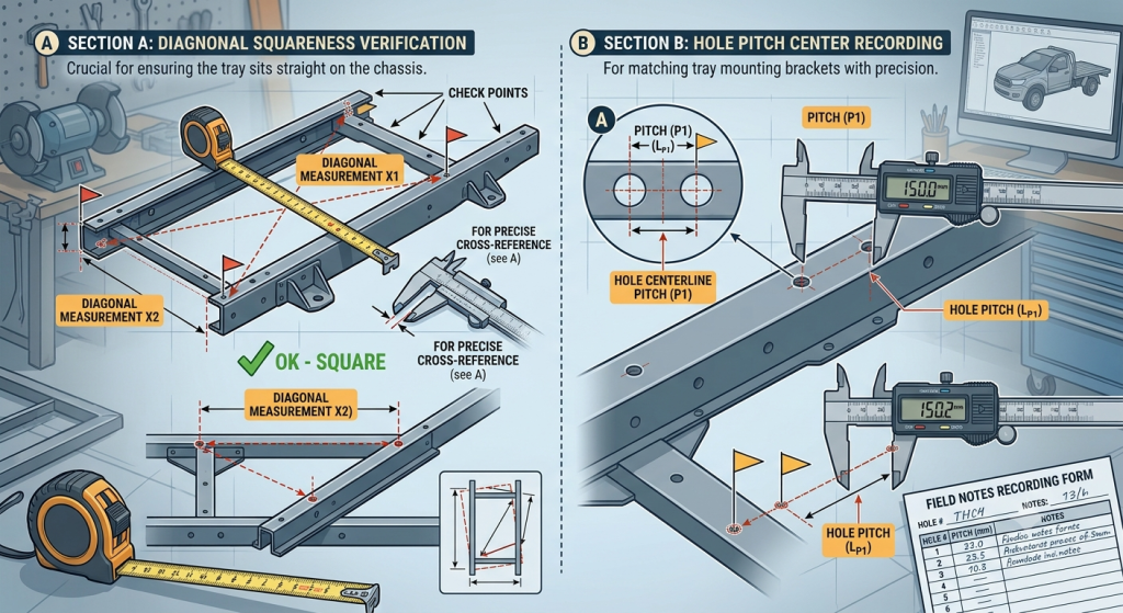
Log the longitudinal and vertical distances between every factory mounting bracket on the frame. Master how to measure ute tray fitment by recording bolt hole diameters and offset heights relative to the top rail.
Mark the center line of the rear axle on the chassis rails. Knowing how to measure ute tray fitment around the rear axle helps locate the deck load center directly over the springs.
Measure diagonally from the left front chassis bracket to the right rear chassis bracket, then swap sides. Equal diagonal dimensions confirm your frame is square, a critical check when learning how to measure ute tray fitment.
Measure vertical distance from the top of the tire tread to the underside of the main runners at full suspension bump-stop compression. This step in how to measure ute tray fitment prevents tire rubbing.
Measure the angle, projection, and hose diameter of the factory fuel filler assembly. Knowing how to measure ute tray fitment ensures your new tray floor leaves sufficient access for refueling.
When applying the rules of how to measure ute tray fitment, reference these standard dimensional parameters across common 4WD vehicle layouts:
| Vehicle Configuration | Recommended Tray Length | Standard Rail Outer Width | Cab-to-Tray Gap Range | Max Allowable Overhang |
| Dual Cab Utility (HiLux/Ranger) | 1,500mm – 1,800mm | 1,000mm – 1,080mm | 30mm – 50mm | 60% of Wheelbase Length |
| Extra Cab / Space Cab | 1,950mm – 2,100mm | 1,000mm – 1,080mm | 30mm – 50mm | 60% of Wheelbase Length |
| Single Cab Workhorse | 2,200mm – 2,400mm | 1,000mm – 1,080mm | 30mm – 50mm | 60% of Wheelbase Length |
| 70 Series LandCruiser Dual Cab | 1,800mm – 1,900mm | 920mm – 960mm | 40mm – 60mm | 60% of Wheelbase Length |
| 70 Series LandCruiser Single Cab | 2,400mm – 2,500mm | 920mm – 960mm | 40mm – 60mm | 60% of Wheelbase Length |
Executing accurate measurements when learning how to measure ute tray fitment requires the right measuring equipment:
                [ Recommended Tooling for Chassis Dimensioning ]
                                       │
  ┌────────────────────────────────────┴────────────────────────────────────┐
  ▼                                                                         ▼
[ Primary Precision Measuring Tools ]                     [ Verification & Alignment Tools ]
• 8m Heavy-Duty Steel Tape Measure                        • Plumb Bob or Optical Drop Line
• Digital Vernier Caliper (0.01mm resolution)            • Laser Level / Digital Angle Finder
• Steel Framing Square (600mm x 400mm)                    • Chalk Line & Surface Marking Paint
• Telescopic Trammel Bar for Diagonals                    • Vehicle Alignment Jack Stands
Using digital vernier calipers is important when following how to measure ute tray fitment steps for bracket hole diameters and plate thickness. Measuring bracket bolt hole diameters ensures subframe bolts fit securely without slop.
When learning how to measure ute tray fitment, a telescopic trammel bar with pointed scribes provides precise diagonal measurements across chassis mounts, helping identify frame twists before fabrication begins.
Follow this systematic sequence to complete a full chassis measurement for custom tray fitment.
1.Prepare Vehicle and Clear Chassis Surface:Park vehicle on flat ground, strip tub body, and clean chassis rails.
Park your vehicle on a level concrete workshop floor. Remove the factory tub or old tray assembly, then clean all road grit and rust off the chassis frame before learning how to measure ute tray fitment.
2.Set Primary Longitudinal Datum Points:Establish cab centerline, rear axle center, and cab clearance gap.
Mark the cab centerline and rear axle center onto the frame rails with a paint pen. Record these base points as step two in how to measure ute tray fitment.
3.Record Chassis Mounting Bracket Dimensions:Measure outer rail width, bracket hole centers, and vertical offsets.
Measure the distance between left and right mounting brackets using vernier calipers. Document bracket hole pitch and vertical height to complete step three of how to measure ute tray fitment.
4.Verify Frame Squareness Across Diagonals:Measure corner-to-corner diagonals across mounting bracket centers.
Measure diagonally from left-front to right-rear brackets, then right-front to left-rear brackets. Equal dimensions confirm chassis squareness, an essential step in how to measure ute tray fitment.
5.Check Overhang Rules and Clearances:Calculate rear overhang, check mudguard clearance, and map wiring path.
Calculate maximum legal rear overhang from the rear axle center. Measure vertical tire compression travel and map wiring loom routing to finish how to measure ute tray fitment.
explore our complete range of 4x4 armor, side steps, and rock sliders
Understanding how to measure ute tray fitment requires strict compliance with vehicle modification regulations. In Australia, tray dimensions must comply with standards published by the Federal Register of Legislation under Australian Design Rules ADR 13/00 (Installation of Lighting) and ADR 42/00 (General Safety Requirements).
                  [ ADR Safety Compliance Criteria ]
                                    │
   ┌────────────────────────────────┼────────────────────────────────┐
   ▼                                ▼                                ▼
[ Maximum Rear Overhang Limit ]  [ Mudguard Tire Coverage Angle ] [ Rear Lamp Projection Angles ]
• Must not exceed 60% of wheel   • Mudguards must cover full tire  • Tail lights must remain visible
  base or maximum 3.7 meters      tread width and 45-deg rear angle  at mandatory 45-degree angles
Avoiding common errors when learning how to measure ute tray fitment saves significant time and re-work during installation:
Reviewing real-world applications highlights the importance of mastering how to measure ute tray fitment:
Use this convenient reference checklist when learning how to measure ute tray fitment: